Zero blaster
Introduction
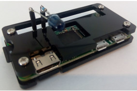
What is pirblaster?
- a raspberry pi with an infrared LED hooked up to the gpio pins.
- pirblaster makes a pi act as a remote control for your TV etc.
Why did you made pirblaster?
- We have a TV, SetopBox and a Amplifier, that all came with their own remote control.
And if you want to watch TV, they all need to be on, switched to the right inputs and at
a normal sound level.
And if you want to watch DVD, the SetopBox can be switched off but the TV must remain on,
and the DVD player must be at the right input.
It takes a fair amount of joggling with 3 remotes to get it right. And then you have to explain
to the rest of the family what they have to do in order to watch TV, DVD, listen to the radio and so on.
So we bought a Logitec Harmony, with which you can do it all, with just one remote.
Everybody happy, easy as pi. Until i dropped it and it broke....
So we bought a new one. And after a while it broke too.. :-(
And one of the annoying things with the Harmony was that it had no idea in which state
the devices were, if you switched them off manually, or selected an input by hand.
It took some time to get everything right again after the devices and the remote became out of sync.
What can you do with pirblaster?
- control your TV, DVD player etc.
- Make activities, like "Watch Tv" and have all devices on and on the right inputs with one button.
- Have the TV on and at the right channel in time for your favorite show. ( just make a cronjob )
- The gui is a webserver running on the pi, so you can control your devices from your tablet, smartphone or desktop computer.
(or pretty much any device that runs a browser)
How did you make it?
- The first thing i did was building a receiver, so i could record the pulses from the
original remote controls. ( schema1.txt , courier 10 )
And as soon as i put the samples in a spreadsheet and made a graph of them,
i had some clue on what the frames looked like. With some googling i found information on the used protocol.
It happened to be r-step, and with that info i was able to control my Motorola Vip1850 setop box.
And for the rest of the equipment it went the same, the Philips Pfl3258h uses Rc6 and the Sony Bdve280 uses sirc.
The initial program used wiringPi, a great library to make access to gpio easy.
I used the hardware PWM of the pi to generate the carrier and used another pin to modulate that carrier.
That first version worked quiet well. about 98% of the send commands where received OK by the equipment.
But, linux, being multiuser, multi-process, has sometimes other things to do and about 2% of the time, the timing
in the frames was too bad to be recognized by the equipment.
So instead of switching the TV to channel 123 it would sometimes switch to channel 12 or 23.
In a kernel module, you can temporary switch off interrupts, so you get a much better timing within the frames
and now way over 99% of the commands are recognized.
Another approach would be writing an interrupt handler and have the pwm pulses trigger interrupts and count the triggers.
It would make it even more accurate i guess, the frames would be a number of pulses width instead of a certain time.
My guess is that that is the way the original remotes do it, a zero being no carrier for x pulses and a one being carrier on for y pulses
And after the frame you would disable the pwm, so the system is not flooded with interrupts.
How do i make it?
- I think best way is to start with the Receiver (schema2.txt). Unless you happen to have one of the remote controls of which the codes are included,
you have to capture what the original remote is sending and analyze that.
You can use a breadboard, or make a small test print with strips, it is not too complicated.
Once the print is ready, hook the print up to the pi, aim your remote control at the IR-photo diode, and see if the red LED flickers when you press a button on the remote.
(if the red LED is already flickering or on, make the surrounding darker, dim some lights, or place a black tube over the IR LED. )
If it flickers, great! you build the print well, and hooked at least the power leads up to the right pins.
The wave length of IR-photo diode should be in the range of the wave length of your devices.
If you can't find the wavelength, try a photodiode with a 940 nm wavelength, it will most likely just work.
If the red LED does not flicker, you can check if your remote is sending light pulses by aiming it at the camera of your mobile phone or tablet.
Unlike the human eye, these camera's are usually sensitive to IR light, so you should see some flickering on your screen.
If you are sure the remote is sending pulses, check the print again carefully.
Record some pulses.
- Download the tarball, it is located at http://pirblaster.kapitein.org/downloads/pirblaster_source_0.0.1.tgz
Untar the tarball somewhere. ( your home directory is a good choice; untar with tar -xzvpf /some/path/pirblaster_source_0.0.1.tgz )
go to the Receive directory and create the Receive executable:
gcc -Wall -Werror -pedantic -g -o Receive Receive.c
The receiver program will wait for the first pulse and then start recording the pulses.
After the recording is over, it will send the samples to stdout.
So make sure the red LED is off and not flickering and then start the Receive program.( as root )
Aim your remote control at the IR-photo diode and press and hold a button. ( mute or power are good choices )
Record a few frames and analyze them, by redirecting the output to a file and import it in a spreadsheet and
making a graph of it.
I recommend using libreoffice –calc and make a X/Y scatter diagram with type "points and lines" and line type stepped and the property "start with horizontal line".
select first row has label, to get the timing at the bottom line.
That way you will see the frame the best.
( there is a sample provided at Doc/Motorola/Vip1850/MotorolaVip1850PowerToggle.ods )
By zooming out, you get a good idea about how many frames there are.
And by zooming in you get more details about the structure of one frame.
The timestamps are in microseconds, but the resolution is much lower, so you might or might not see the individual carrier pulses.
But you should be able to see the frames.
Often a frame consists of a header, that will initialise the hardware, an address, that
corresponds with the device you want to control, a command ( poweron, mute etc ) and a
trailer that will switch off the carrier.
A too simple graph of what a frame might looks like: < header >< address >< command >< trailer >
___________ ______ ___ ______ ___ ___
________| |____| |___| |___| |______| |___| |________
In reality there will be much more pulses, depending on the protocol the remote control uses.
And frames are often repeated, and might have a toggle bit in the header to distinguish between a first frame and a repeated frame.
If you have information on brand, model, pulsewidth, Header length, frame length, inter frame gap etc, try to google it.
RC5 and RC6 are common, and so are the NEC codes.
And take a look at the http://lirc.sourceforge.net/remotes website, they have info on a lot of remotes.
Once you know how a frame is build, you are ready to build a frame yourself.
A frame is just a string that contains the information to send a command to your TV.
The string is a series of numbers, separated by commas. They represent the state of the carrier.
So after you found out how one command looks like, make a string with that command.
0,1234,1,800,0,800,1,400,0,400,-1,-1 would mean: CarrierOff for 1234 usecs, CarrierOn for 800 usecs, CarrierOff for 800 usecs,
CarrierOn for 400 usecs and CarrierOff for 400 usecs. And so on. Make sure the last two values of the string are -1,-1
as that will tell the module that the command is complete and can be sent.
(There should be no spaces in the string, just numbers and commas)
Since the commands for one device normally have the same header ( perhaps with a different toggle bit ) and the same address
and the same trailer, it makes sense to have a few files and build your frames with those files.
Without too much explanation, it would make sense to do:
cat header toggle address command000 trailer > string000
cat header toggle address command001 trailer > string001
etc.
( an example of this approach can be found in Scripts/Akai/unkown20160911 )
If you know the number of bits in the command part of the frame,
you can make a file for every possible command and see what command does what.
( if there are 8 bits in a command, you would have 256 possible commands )
That way you might be able to find "hidden" commands, for which no button exists on the original remote control.
installing the rest of the software.
- Make sure you have autoconf: sudo apt-get install -y autoconf
The rest of the software consists of a kernel module and a control program.
The kernel module talks to the GPIO hardware and creates a /dev/MyIrMod device.
The control program sets the frequency and dutycycle of the carrier
and is called InitCarrier.
Install the kernel sources from https://www.raspberrypi.org/documentation/linux/kernel/building.md
make sure you can access the running config and run:
sudo modprobe -v configs
copy the running config of your pi to the config file:
zcat /proc/config.gz | sudo tee /usr/src/linux/.config > /dev/null
follow the instructions from the above link, but instead of "make <hw>_defconfig" do:
cd /usr/src/linux
make silentoldconfig
and go with the defaults if some questions pop-up.
for the rest, follow the instructions.
Since we are building it on the pi, we can stop before the crosscompiling section of the link.
Building a kernel on the pi takes a long time,
on a pi zero it took well over 12 hours, so start it in the afternoon in the background and come back the next day.
After installing the kernel is complete you can install the rest of the software.
Go to the directory where you put the software ( i will use "${HOME}"/pirblaster_source in this example )
and type ./bootstrap.sh
This should build the software and the default website to control your devices.
You will get an error about permissions, so the next step has to be done as root:
sudo make install
(to install the module and the website. By default it will put the programs and scripts in /usr/local/pirblaster )
After that, you should change the ownership of /usr/local/pirblaster to your own userid.
( or create a separate user and set the ownership to that id )
sudo chown -R username. /usr/local/pirblaster
( the . after username should be there, it is not a typo )
sudo cp "${HOME}"/pirblaster_source/Kmod/80-MyIrmod.rules /etc/udev/rules.d/
(to copy the udev rule that will create the devicefile when the module is installed )
Clear and display the kernel log with:
sudo dmesg -c
sudo modprobe -v MyIrMod
( to load the kernel module )
and check with lsmod and dmesg that it is loaded.
Now it is time to hookup the IR LED to the pi.
It should be very simple, an IR LED and a 150 Ohm resistor in series.
Make sure the resistor is connected to the anode of the IR LED.
Connect the resistor to pin 12 and the cathode of the IR LED to pin 8. Pin 12 0------------------+
|
|
+-+
|1|
|5|
|0|
|R|
+-+
|
| IR LED
___
\ / ->
V ->
---
|
|
Pin 8 0------------------+
If that all went well, check with your camera if the IR LED is flickering
when you send data to the device.
The software came with a test string, that should make the IR LED flicker.
First make sure the carrier is initialized by running
/usr/local/pirblaster/bin/InitCarrier 20 50
( 20KHz with 50% dutycycle )
Then send the test data to the device, in a loop so you have time to aim your camera
You can use this little snippet:
for Burst in $( seq 1 60 ); do
cat /usr/local/pirblaster/scripts/TestIRLED.data > /dev/MyIrMod
sleep 1
done
If you see the IR LED flicker it is time to celebrate, all the hardware is working!
To test your own string, you can use the same loop as above, but this time with
cat /path/to/your/string001 > /dev/MyIrMod
Check with the camera if the IR LED is pulsing as it should.
If not, check with dmesg if there are any error messages.
The IR LED should be off after sending a command. Check with the camera if it is.
If it is on, try reversing the connections to the IR LED.
Assuming everything is working it is now time to send your first command!
Put the pi in the proximity of the device you want to control ( 30 cm or so )
[for simplicity i will use TV for the device to control, but it can be anything with an IR remote control]
And aim the IR LED at the place were you think the IR Receiver is on the TV.
Now cat /path/to/your/string001 > /dev/MyIrMod and see if the TV reacts.
( sometimes a TV will acknowledge a command by blinking a red LED or something )
If it does, you can try to build different frames (VolumeUp, VolumeDown etc).
Now what?
- If you have all the commands for all your devices, you can start to compose activities, like "WatchTv" or "ListenRadio".
the /usr/local/pirblaster/scripts directory is the place where you can place your own scripts.
the scripts already there are nothing more than examples on what it might look like.
They are not supposed to work for you, you have to build your own.
Look at them for inspiration and then overwrite them with your own scripts, for your own devices.
If you install lighttpd, you can use the cgi scripts to control your devices from your mobile phone or tablet.
The cgi scripts call the shell scripts so you have to tweak the files to match your own setup.
If you have all the codes for your device, please send them to me, so i can include them in the software.
That way we can build a database with all the different codes. ( pirblaster AT kapitein D0T org )
Please use Brand/Model/ButtonName, like Motorola/Vip1850/PowerToggle so we can easily update the table with
supported brands and models.
installing lighttpd
- sudo apt-get install lighttpd
sudo lighty-enable-mod cgi
add cgi to /etc/lighttpd/lighttpd.conf: static-file.exclude-extensions = ( ".php", ".pl", ".fcgi", ".cgi" )
and change the documentroot: server.document-root = "/var/www"
and in /etc/lighttpd/conf-enabled/10-cgi.conf assign bash to cgi scripts: cgi.assign = ( ".cgi" => "/bin/bash" )
You might like to add server.breakagelog = "/var/log/lighttpd/breakage.log" to this file too, to help debugging the scripts
The scripts and html pages refer to "fqdn.of.your.pi", so find and replace that string with the fully qualified domain name
of your pi, or its ip address.
Make sure the table directories are writeable by the lighttpd proces.
( find /usr/local/pirblaster -type d -name tables -exec chmod a+rw {} \; )
After all this, restart lighttp: sudo service lighttpd restart
Integration
- You can make some additional hardware to detect the state of your devices,
and read them with cron, so you can write the state of the device in a statefile and check if a device is on or off.
This will keep the pi and the devices almost always "in sync"
A simpler way is to monitor the switchport the setopbox is connected to with SNMP and
use that to determine the state of your devices.
Or use ping to check whether a device is on or off.
If you want to control devices in a closed cabinet, you can use schema2.txt and use one LED per cabinet.
directions
- It would be great if someone more knowledgeable could make an overlay, so you could just add the overlay to your config.txt
and kids could write programs in scratch.
That way they could combine a TV that is very real with something as abstract as a program.
Bitcoin Donations are welcome:
- 1E8G3pBpHu76ysQ1qJ2mMJqcUPjvvynrDw
so i can buy some more pi's
Supported Devices
| Brand | Model | Device | Path |
| Philips | Pfl3258h | TV | Philips/Pfl3258h |
| Motorola | Vip1850 | SetopBox | Motorola/Vip1850 |
| Sony | Bdve280 | HomeTheater | Sony/Bdve280 |
Bugs
Schema's
The Receiver. schema1.txt, courier10.
+-----------------------O Pin 1
| |
IR-photo | |
diode | |RED LED
___ ___
-> ^ \ / ->
-> / \ v ->
--- ---
| |
| |
+-+ +-+
| | |1|
|4| |0|
|7| |0|
|K| |E|
+-+ +-+
| |
| |-----------O Pin 11
| |
| b| /c
+---------|< BC547
| | \e
| |
| |
| |
+-+ |
|4| |
|7| |
|0| |
|K| |
+-+ |
| |
| |
| |
+-----------+-----------O Pin 9
A Sender for multiple LEDs, schema2.txt, courier 10
Pin 4 O----------------------------------------------+
|
|
+-+
|1|
|0|
|0|
|R|
+-+
|
+----------+
| IR LEDs |
If you need +--------------+ |
more then one | | | |
IR LED ___ ___ ___ |
you can use this \ / -> \ / -> \ / -> |
driver. V -> V -> V -> |
--- --- --- |
| | | |
| | | |
+-+ +-+ +-+ |
|1| |1| |1| |
|5| |5| |5| |
|0| |0| |0| |
|R| |R| |R| |
+-+ +-+ +-+ |
| | | |
| | | |
+--------------+ |
| |
Carrier +-------+ b| /c |
Pin 12 O----| 1 K |-------------+-------+---------|< BD137 |
+-------+ | | | \e |
| | | |
| | | |
| | | |
| | | |
Modulation +-------+ b| /c | | |
Pin 8 O----| 10 K |-----------|< BC547 | | |
+-------+ | | \e | | |
| | | | |
+-+ | +-+ | |
|1| | | | | ===== 100uF
|0| | |1| | =====
|0| | |0| | |
|K| | |K| | |
+-+ | +-+ | |
| | | | |
| | | | |
| | | | |
Pin 6 O------------------+-------+-------+-----------+----------+
ModuleOptions:
- There are some module options available, they are:
debug=1 This will turn on debugging, check the results with dmesg. Only use this option if you experience problems sending commands.
invert=1 This will invert the gpio pin and can be used if you use different hardware to drive the IR LED.
the options need to be given at module load time, so modprobe -v MyIrMod debug=1 invert=1.
You can add the module to /etc/modules: MyIrMod debug=0 invert=1
TODO:
- tons of stuff
- make a program to analyze the received samples and give some useful info on the files


 1.8.10

